
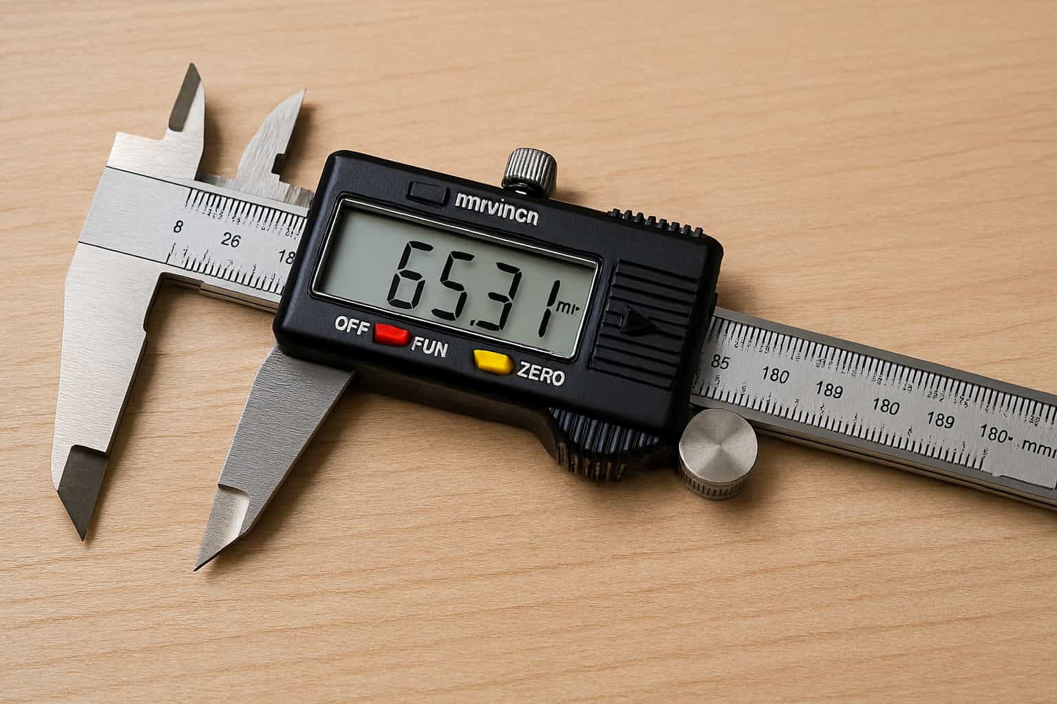
Taking precise measurements is a fundamental step when restoring, replacing, or customizing three-piece rims. Each dimension directly influences compatibility, safety, and mounting performance on your vehicle.
Width Measurement: Technique for Each Component
Correctly determining the width of the different sections of the rim ensures compatibility with tires and adherence to technical specifications. A rigorous methodology is required to obtain usable values.
Wheel Preparation and Positioning
Place the rim on a perfectly flat and stable surface with the outer barrel facing upwards. This position facilitates access to the measurement areas and ensures the accuracy of readings by eliminating distracting viewing angles.
Specific Measurements by Component
Each element of the modular rim requires an adapted measurement approach to capture its actual usable dimension.
Measurement Protocol for the Outer Rim:
- Position the tape measure or caliper from one inner edge to the other.
- Ensure the measurement is taken perpendicular to the axis of rotation.
- Subtract 1.27 cm (1/2 inch) to compensate for the thickness of the bead seats.
- The result obtained corresponds to the effective width of the rim.
Measurement Protocol for the Inner Barrel:
- Measure the distance between the inner walls of the barrel in a straight line.
- Keep the measuring instrument perpendicular to the central axis.
- Subtract 1.27 cm to obtain the usable dimension.
- This value determines compatibility with braking systems.
Measurement Protocol for the Center Disc:
- Measure the width from one end of the disc to the other.
- Ensure the measurement remains perpendicular to the disc surface.
- No correction is necessary for this dimension.
- This measurement influences the final offset of the assembled rim.
Hardware Measurement: Essential Technical Specifications
The peripheral hardware requires three distinct measurements to precisely identify compatible fasteners for replacement or upgrade. These dimensions determine the structural safety of the assembly.
Threaded Body Diameter
The nominal diameter is measured on the smooth, unthreaded part of the bolt, called the body or shank. Use a digital caliper to ensure accuracy to one-tenth of a millimeter. This value determines the required bore in the rim components.
Total Length Under Head
Measure the distance from the underside of the bolt head to the end of the threaded part. Include the entire thread in your reading to obtain the useful length. Do not incorporate any washers or nuts in this measurement unless they are permanently attached to the fastener.
Thread Pitch
The pitch represents the spacing between two consecutive threads and is generally expressed in millimeters for the metric system. A thread gauge (pitch gauge) allows for rapid identification of this characteristic by testing different values until the perfect match is found. This specification ensures compatibility of the threading and the mechanical strength of the assembly.
Center Bore Measurement: Hub Inner Diameter
The center bore, also referred to as the "inner diameter," defines the diameter of the fitting hole on the vehicle's hub. This critical dimension ensures precise wheel centering and optimal force transmission.
Center Bore Measurement Technique
Place the rim flat on your workbench and use a Vernier caliper or micrometer to capture a reliable measurement. Measure the internal diameter of the center disc from one inner edge to the opposite edge, passing through the exact center. Repeat the operation along a perpendicular axis to confirm the perfect circularity of the bore. The obtained value must precisely match the vehicle's hub diameter to avoid any play that could cause vibrations.
PCD Measurement: Bolt Pattern
PCD (pitch circle diameter) or bolt pattern defines the diameter of the theoretical circle passing through the center of all mounting holes. This fundamental dimension determines the absolute compatibility between the rim and the receiving vehicle.
Tools Required for Bolt Pattern Measurement
Equipment required for accurate measurement:
- Metallic tape measure or rigid graduated ruler
- Specialized bolt pattern gauge (recommended for optimized reliability)
- Caliper for verification measurements
- Calculator for any conversions
PCD Measurement Procedure
Select any mounting hole as a starting point; the measurement does not require evaluating all holes. Measure the distance between the center of this hole and the center of the diametrically opposite hole, ensuring you pass exactly through the central axis of the rim. For configurations with an odd number of fasteners, use the appropriate trigonometric formula or a dedicated gauge. Repeat the operation from another hole to its diagonal opposite to validate the consistency of your first measurement and eliminate potential positioning errors.
Total Diameter Measurement: Overall Width of the Disc
The total diameter, also called "face width," quantifies the complete wheelbase of the center disc between its outer ends. This dimension influences the calculation of the final offset after assembling the three sections.
Face Diameter Measurement Method
Place the wheel flat on your workbench and deploy your Vernier caliper or micrometer. Position the jaws of the instrument to capture the distance between the outer edge of the disc on one side and the opposite outer edge. Ensure that the measurement crosses the exact geometric center of the disc to obtain the actual maximum diameter. This value, combined with the widths of the inner and outer barrels, allows for calculating the total assembled width of the modular rim.